
Introduction
This section focuses on the diagnosis and repair of various accessories such as power side windows, power tailgate windows, power seats, electric door locks, keyless entry systems, rear window defoggers, electric sunroofs, convertible tops, and electrically operated/heated mirrors.
These accessories are essential components of modern vehicles and require regular maintenance and repair to ensure their proper functioning. This chapter provides detailed information on the diagnosis and repair of these accessories, including identifying common problems, testing components, and replacing faulty parts.
By following the guidelines in this chapter, technicians can provide effective and efficient accessory diagnosis and repair services to their clients.
1. Body
The section is divided into four questions that cover diagnosing and repairing problems related to body electrical systems, body hardware, body interior, and body exterior. The topics covered in this chapter are essential for automotive technicians who need to diagnose and repair body-related issues in vehicles to ensure their safe and reliable operation.
This section requires a deep understanding of automotive body systems and the diagnostic tools and techniques needed to troubleshoot and repair them. By mastering the topics covered in this chapter, technicians can become ASE-certified and enhance their knowledge and skills in the field of automotive repair.
Task H.1.1 - Diagnose the Cause of Slow, Intermittent, or No Operation of Power Side Windows and Power Tailgate Windows
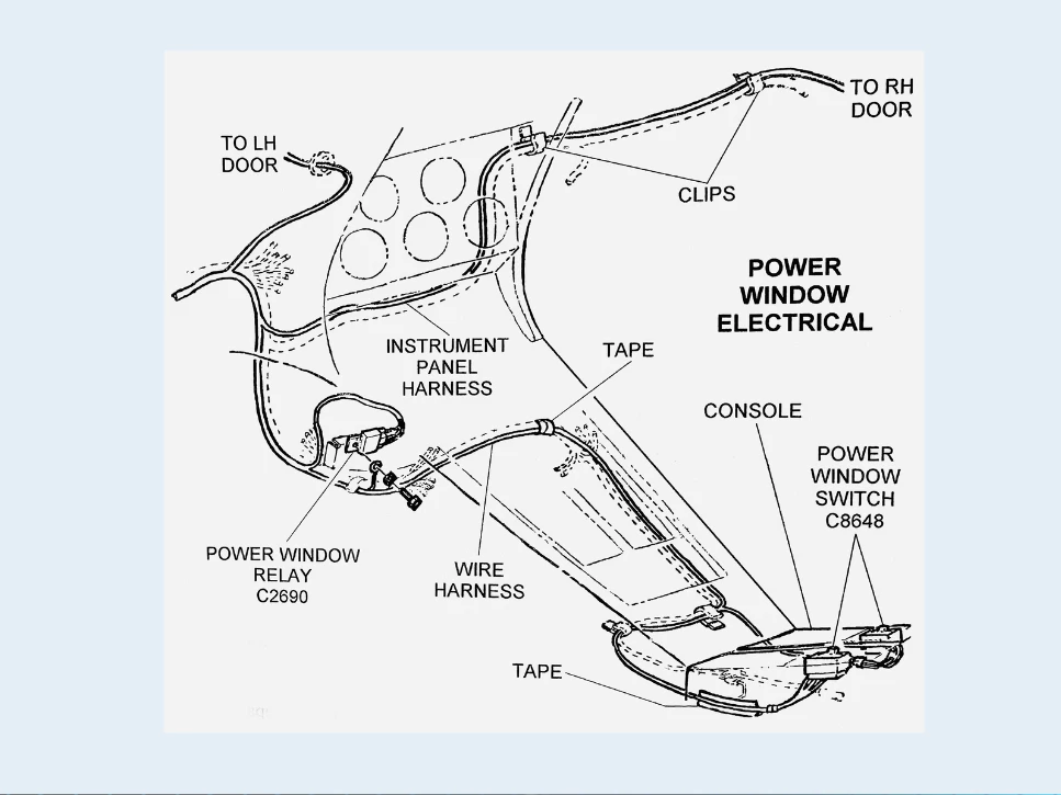
Power windows are a common feature in modern vehicles, and they are usually equipped with a master switch or individual window switches and a window motor in each door. These circuits may also include a window lockout switch to prevent passengers from operating the windows.
When the master switch is placed in the down position, voltage is supplied to the center contact in the switch through the movable switch contact to the brush on the lower side of the commutator. The other brush is grounded through the master switch. Under this condition, the motor moves the window to the down position.
When the up position is selected in the master switch, the current flow through the motor is reversed. Voltage is supplied from the ignition switch circuit breaker and lockout switch to the window switch. If the power windows operate slowly, intermittently, or not at all, the most common causes are poor window track alignment or a buildup of ice on the window.
To diagnose the problem, refer to the wiring diagram for the circuit. Identify all the wires and connectors that are common to the system if all the windows do not work properly. If only one window does not operate correctly, identify only those parts of the circuit that would affect that window.
Testing the power window circuits usually involves inspecting, testing, and repairing or replacing regulators (linkages), switches, controllers, relays, motors, connectors, and wires. Power window circuits usually include a circuit breaker at the motor to prevent motor damage due to high current flow. To test the circuit breaker, use a test light or voltmeter to check for voltage on both sides of the breaker. If voltage is present on one side and not the other, the breaker has tripped and must be reset or replaced.
Window regulators can be tested by removing them from the door and checking for smooth operation. Check the condition of the linkages, and adjust or replace them as necessary. Switches and controllers can be tested with a test light or voltmeter. Check the connectors and wires for damage or corrosion, and replace them as necessary.
Task H.1.2 - Inspect, Test, and Repair or Replace Regulators (Linkages), Switches, Controllers, Relays, Motors, Connectors, and Wires of Power Side Window and Power Tailgate Window Circuits.
To diagnose and repair power window circuits, first, identify the specific problem by referring to the wiring diagram for the circuit. Identify all the wires and connectors that are common to the system if all the windows do not work properly. If only one window does not operate correctly, identify only those parts of the circuit that would affect that window. If the window operates slowly, intermittently, or not at all, check the condition of the window regulator and its linkages. Inspect for damage or wear and adjust or replace them as necessary. Check the motor for smooth operation and excessive current draw, and replace it if necessary. Check the switches and controllers with a test light or voltmeter, and replace them if faulty. Check the connectors and wires for damage or corrosion, and replace them as necessary. If the circuit breaker has tripped, reset it or replace it as necessary. If the problem persists, refer to the wiring diagram for the circuit and check all the wires and connectors that are common to the system. Repair or replace any damaged or corroded wires or connectors.
Task H.1.3: Diagnose the Cause of Slow, Intermittent, or No Operation of Power Seat and Seat Memory Controls.
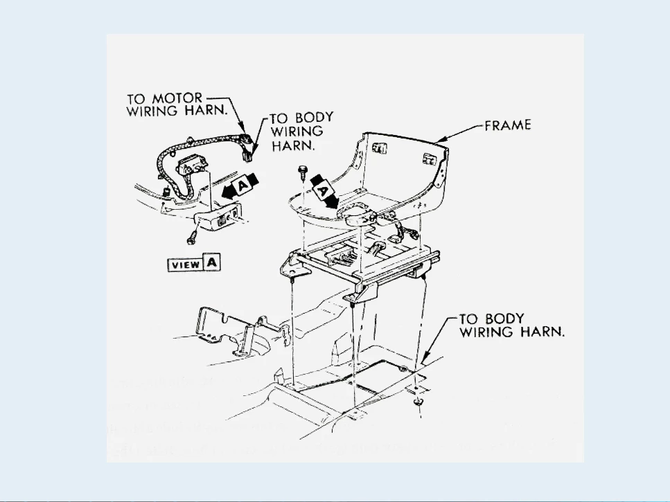
Power seats are equipped with motors that control the vertical and horizontal movement of the seat. These motors are connected through gearboxes and cables to the seat track mechanisms. The front and rear switches have upward and downward positions, and the center switch has forward and rearward positions. When any of the switches are pressed, voltage is supplied to the appropriate motor in the proper direction, and the motor moves the seat in the desired direction.
If the power seat operates slowly, intermittently, or not at all, the most common causes are poor seat track alignment or a buildup of dirt on the tracks. To diagnose the problem, refer to the wiring diagram for the circuit. Identity all the wires and connectors that are common to the seat movement that is not working correctly. If none of the seat functions work, suspect an open to the control switch.
Testing and repairing power seat circuits involves inspecting, testing, adjusting, and repairing or replacing power seat gearbox, cables, switches, controllers, sensors, relays, solenoids, motors, connectors, and wires. Power seat circuits usually include a circuit breaker at the motors to prevent motor damage due to high current flow.
To test the circuit breaker, use a test light or voltmeter to check for voltage on both sides of the breaker. If voltage is present on one side and not the other, the breaker has tripped and must be reset or replaced.
To test the gearbox and cables, remove them from the seat and check for smooth operation. Inspect the condition of the switches, controllers, sensors, and relays and replace them if faulty. Check the connectors and wires for damage or corrosion and replace them as necessary.
Task H.1.4: Inspect, Test, Adjust, and Repair or Replace Power Seat Gear Box, Cables, Switches, Controllers, Sensors, Relays, Solenoids, Motors, Connectors, and Wires of Power Seat Circuits and Seat Memory Controls.
Power seats are equipped with a variety of components, including gearboxes, cables, switches, controllers, sensors, relays, solenoids, motors, connectors, and wires. These components can become damaged or worn over time, resulting in slow, intermittent, or no operation of the power seat or seat memory controls.
To diagnose and repair power seat circuits, first, identify the specific problem by referring to the wiring diagram for the circuit. Identify all the wires and connectors that are common to the seat movement that is not working correctly. If none of the seat functions work, suspect an open to the control switch.
Testing and repairing power seat circuits involves inspecting, testing, adjusting, and repairing or replacing power seat gearbox, cables, switches, controllers, sensors, relays, solenoids, motors, connectors, and wires. Power seat circuits usually include a circuit breaker at the motors to prevent motor damage due to high current flow.
To test the circuit breaker, use a test light or voltmeter to check for voltage on both sides of the breaker. If voltage is present on one side and not the other, the breaker has tripped and must be reset or replaced.
To test the gearbox and cables, remove them from the seat and check for smooth operation. Inspect the condition of the switches, controllers, sensors, and relays and replace them if faulty. Check the connectors and wires for damage or corrosion and replace them as necessary.
Task H.1.5: Diagnose the Cause of Poor, Intermittent, or No Operation of Rear Window Defogger.
The rear window defogger is an essential accessory that helps to keep the rear window clear of condensation and frost, providing the driver with a clear view of the road behind. If the rear window defogger operates poorly, intermittently, or not at all, it can be caused by a variety of problems.
When the rear defogger switch is pressed, a signal is sent to a solid-state timer. When this signal is received, the timer grounds the relay winding. Under this condition, the relay supplies voltage to the defogger grid. When the relay is closed, current flows through the light emitting diode (LED) indicator to the ground. After a preset time, the timer opens the relay, shutting off the grid current.
To diagnose the cause of poor, intermittent, or no operation of the rear window defogger, begin by checking the fuse and the switch. If both the fuse and switch are functioning correctly, use a test light or voltmeter to check for voltage at the defogger grid. If voltage is present, the grid is most likely damaged or broken. In this case, a special compound is available to repair open circuits in the grid tracks.
Testing and repairing rear window defogger circuits involves inspecting, testing, and repairing or replacing switches, relays, timers, controllers, window grids, connectors, and wires. To test the grid tracks, use a 12V test light and move it across a grid track from the power supply side to the ground side. The light should gradually become dimmer. If the test light goes out partway across the grid, the grid has an open circuit.
Check the condition of the switches, relays, and timers and replace them if faulty. Check the connectors and wires for damage or corrosion and replace them as necessary.
Task H.1.6: Diagnose the Cause of Poor, Intermittent, or No Operation of Electric Door and Hatch/Trunk Locks
Electric door and hatch/trunk locks are vital components for ensuring both security and convenience in modern vehicles. When these locks exhibit poor performance, intermittent issues, or fail to operate altogether, it can be attributed to a range of underlying problems.
Most electric door lock circuits have small electric motors to operate the door locks. When either door lock switch is pushed to the lock position, voltage is supplied to all the door lock motors in the proper direction to provide lock action. If either door lock switch is pushed to the unlock position, voltage is supplied to all the door lock motors in the opposite direction to provide an unlock action.
To diagnose the cause of poor, intermittent, or no operation of the electric door and hatch/trunk locks, begin by checking the fuse and the switch. If both the fuse and switch are functioning correctly, use a test light or voltmeter to check for voltage at the door lock motors. If voltage is present, check the condition of the actuators/solenoids and replace them if faulty.
If all the door locks are completely inoperative, check the fuse. When all the door locks are inoperative in the lock or unlock mode, test the lock and unlock relays and connecting wires. If one door lock motor is inoperative, test the individual motor and connecting wire, and check the lock mechanism for a binding condition.
Testing and repairing electric door and hatch/trunk lock circuits involves inspecting, testing, and repairing or replacing switches, relays, controllers, actuators/solenoids, connectors, and wires. Check the condition of the switches, relays, and controllers and replace them if faulty.
Task H.1.7 - Diagnose the Cause of Poor, Intermittent, or No Operation of Keyless and Remote Lock/Unlock Devices.
Keyless and remote lock/unlock devices provide added convenience and security for modern vehicles. If the devices operate poorly, intermittently, or not at all, it can be caused by a variety of problems.
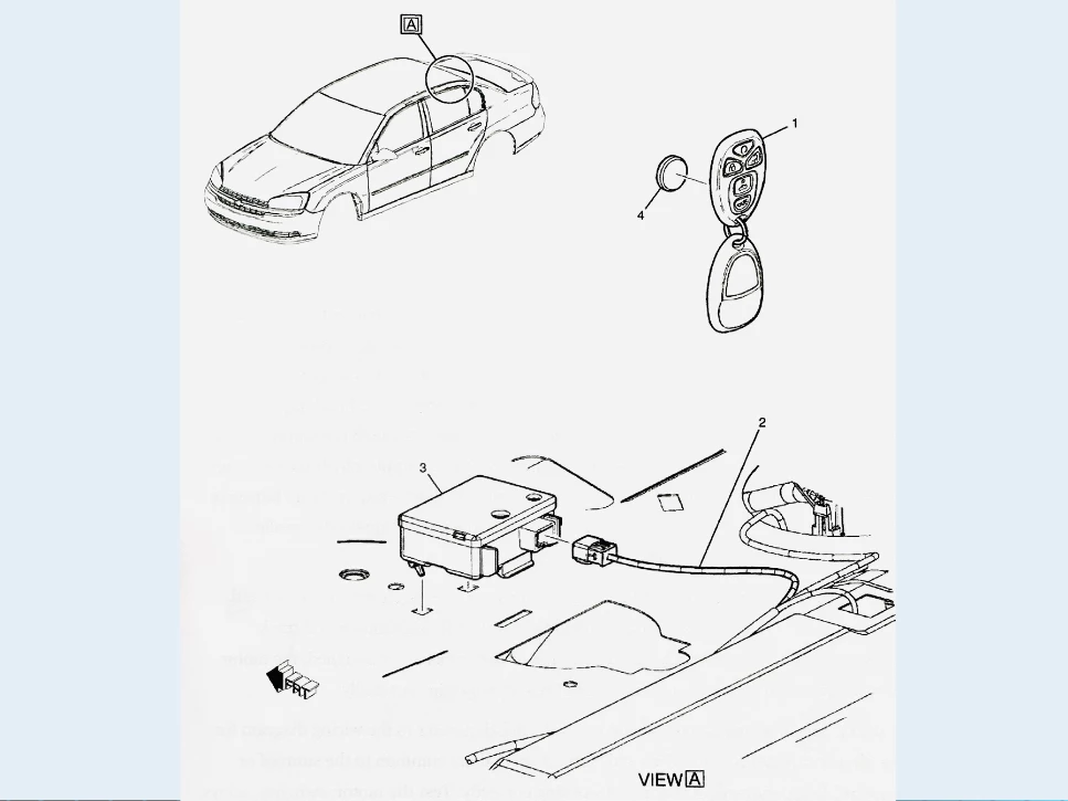
The remote keyless entry module is connected to the power door lock circuit. A small remote transmitter sends lock and unlock signals to this module when the appropriate buttons are pressed on the remote transmitter. When the handheld remote transmitter is a short distance from the vehicle, the module responds to the transmitter signals.
When the unlock button is pressed on the remote transmitter, the module supplies voltage to the unlock relay winding to close these relay contacts and move the door lock motors to the unlock position. When the unlock button is depressed on the remote transmitter, the locks will unlock, and the interior lights will illuminate on most systems. Then the remote keyless entry module will turn off the interior lights after approximately one minute or when the ignition is turned on.
To diagnose the cause of poor, intermittent, or no operation of keyless and remote lock/unlock devices, begin by checking the battery in the remote transmitter. If the battery is good, use a test light or voltmeter to check for voltage at the module and the lock/unlock relays. If voltage is present, check the condition of the actuators/solenoids and replace them if faulty.
Testing and repairing keyless and remote lock/unlock device circuits involves inspecting, testing, and repairing or replacing components, connectors, controllers, and wires. Check the condition of the components and replace them if faulty. Check the connectors and wires for damage or corrosion and replace them as necessary.
Power lock circuits usually control the action of a solenoid. The movement of the center core of the solenoid controls the action of the lock levers and arms. The best way to diagnose a power lock problem is to refer to the wiring diagram for the circuit. Many switches and solenoids are involved, and to quickly determine the problem you should identify all of the wires and connectors that are common to the lock that is not working properly. If none of the locks work, suspect an open to the control switch.
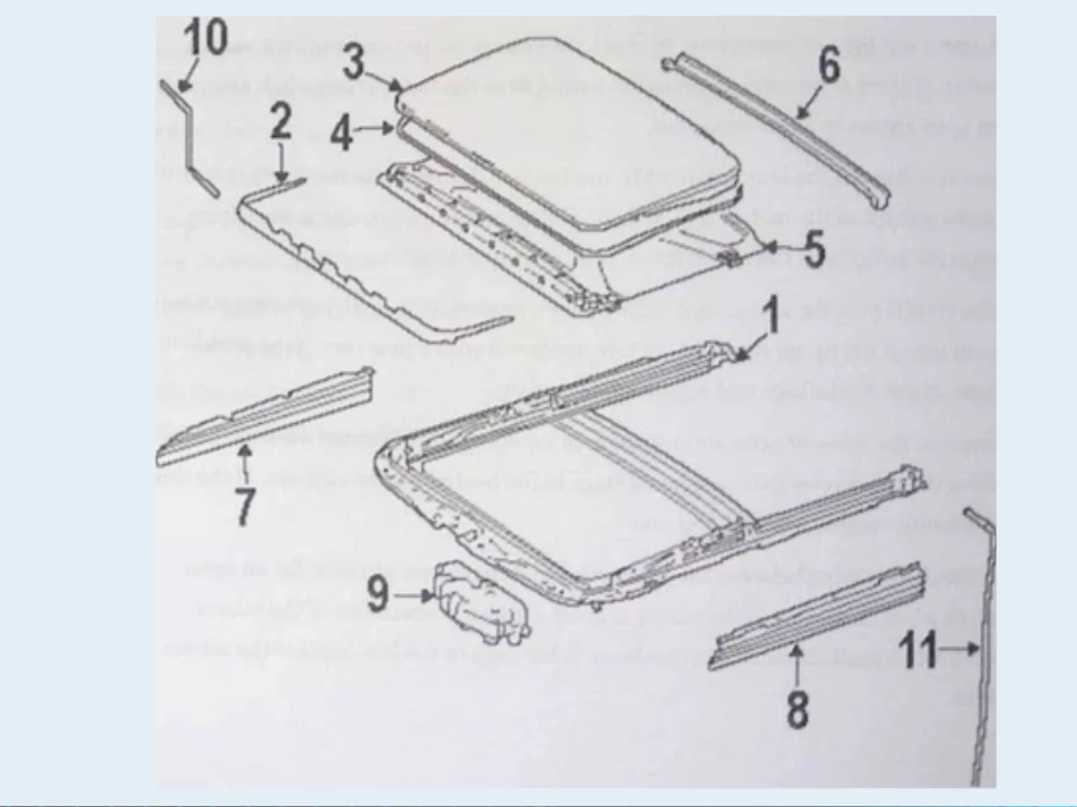
Task H.1.8 - Diagnose the Cause of Slow, Intermittent, or No Operation of the Power Sunroof and Convertible Top.
Power sunroofs and convertible tops provide added comfort and style to modern vehicles. If the sunroof or convertible top operates slowly, intermittently, or not at all, it can be caused by several reasons.
When the open sunroof switch is pressed, the open relay winding is grounded through the switch contacts. Under this condition, the relay contacts close and supply voltage to the sunroof motor brush. The other motor brush is connected through the close relay contacts to the ground. Current now flows through the motor, and the motor opens the sunroof.
If the close button is pressed, the close relay winding is grounded through the close switch contacts. Under this condition, the close relay contacts supply voltage to the sunroof motor in the opposite direction to close the sunroof. The convertible top system contains a dual switch, pump motor, hydraulic cylinders, and linkages from these cylinders to the convertible top.
When the down button is pressed, voltage is supplied through these switch contacts to a motor brush. The opposite motor brush is grounded through the up contacts. Under this condition, current flows through the motor, and the motor drives the pump. With this motor rotation, the pump supplies hydraulic pressure to the proper side of the cylinder pistons to move the top downward. If the up button is pressed, the motor and pump rotation are reversed, and the pump supplies hydraulic pressure to the upward side of the cylinder pistons.
To diagnose the cause of slow, intermittent, or no operation of the electrical sunroof and convertible top, begin by checking the condition of the lift mechanisms and track alignments. If the lift mechanisms are binding or the tracks are misaligned, the motor may not function properly, and the circuit breaker may trip repeatedly.
If the lift mechanisms and tracks are in good condition, refer to the wiring diagram for the circuit and identify the wires and connectors that are common to the sunroof or convertible top movement that are not working correctly. Test the motor, switches, relays, controllers, connectors, and wires to determine the problem.
Testing and repairing a power roof and convertible top circuits involves inspecting, testing, and repairing or replacing motors, switches, controllers, relays, connectors, and wires. Power top and sunroof circuits are subject to high current flow, and a motor draws high current anytime it rotates slowly.
This type of mechanical interference can cause a motor to burn up, a circuit breaker to trip repeatedly or damage the circuit’s wiring. Check the condition of the components and replace them if they are faulty. Check the connectors and wires for damage or corrosion and replace them as necessary.
Identify what parts of the circuit are involved with the function that is not working correctly and diagnose those switches, wires, and connectors. If the sunroof or top does not move in any direction, suspect an opening in the control circuit.
Task H.1.9 - Diagnose the Cause of Poor, Intermittent, or No Operation of Electrically Operated/Heated Mirror.
Electrically operated/heated mirrors are common accessories in modern vehicles. They can improve visibility and driver safety by providing a clear view of the surroundings. If the mirrors are not working correctly, it can be caused by a variety of problems, such as faulty motors, switches, controllers, relays, connectors, or wires.
To diagnose the cause of poor, intermittent, or no operation of electrically operated/heated mirrors, begin by checking the fuse that supplies voltage to the power mirror switch assembly. If the fuse is blown, replace it with a new one of the same rating. Next, use a test light or multimeter to check the voltage at the power mirror switch assembly. If there is no voltage, check the wiring from the fuse to the switch assembly for an open circuit or a bad connector.
If there is voltage at the switch assembly, use the switch to operate the mirrors and check the voltage at the motor. If there is no voltage at the motor, check the wiring between the switch and the motor for an open circuit or a bad connector.
If there is voltage at the motor, check the motor’s operation by applying voltage directly to the motor. If the motor does not operate, replace it with a new one. If the motor operates, check the linkage and adjust it if necessary.
To diagnose the cause of poor, intermittent, or no operation of heated mirrors, begin by checking the timer relay that supplies voltage to the heated mirror element. If the timer relay is faulty, replace it with a new one.
Next, check the wiring between the timer relay and the mirror element for an open circuit or a bad connector. If the wiring is good, check the resistance of the mirror element with a multimeter. If the resistance is too high or too low, replace the mirror element.
Task H.1.10 - Inspect, Test, and Repair or Replace Motors, Heated Mirror Grids, Switches, Controllers, Relays, Connectors, and Wires of Electrically Operated/Heated Mirror Circuit.
Electrically operated/heated mirrors are complex systems that require regular maintenance and inspection to ensure their proper function. Troubleshooting and repairing electric heated mirror circuits involves inspecting, testing, and repairing or replacing motors, heated mirror grids, switches, controllers, relays, connectors, and wires.
To inspect and test the heated mirror grid, use a multimeter to check the resistance of the mirror element. If the resistance is too high or too low, replace the mirror element.
To troubleshoot the motor, use a test light or multimeter to check the voltage at the power mirror switch assembly and at the motor. If there is voltage at the switch assembly but not at the motor, check the wiring between the switch and the motor for an open circuit or a bad connector.
To inspect and test the switches, controllers, relays, connectors, and wires, refer to the wiring diagram for the circuit and identify the wires and connectors that are common to the mirror movement that is not working correctly. Test the components to determine the problem.
Check the connectors and wires for damage or corrosion and replace them as necessary. Replace any faulty components.
2. Miscellaneous
Section 2 in the ASE A6 Test Task List is titled “Miscellaneous” and covers a variety of tasks related to troubleshooting issues with various accessories in a vehicle. This chapter includes tasks such as diagnosing poor sound quality in audio systems, inspecting and repairing power antenna circuits, and testing and repairing cruise control circuits. ASE A6 Technicians must be familiar with these tasks and follow the standard diagnostic procedures to ensure the proper functioning of accessories in a vehicle. This chapter highlights the importance of thorough inspection, testing, and repair of accessories to ensure optimal performance and safety on the road.
Task H.2.1 - Diagnose the Cause of Poor Sound Quality, Noise, Erratic, Intermittent, or No Operation of the Audio System; Remove and Reinstall Audio System Component (Unit).
Audio systems are considered very important to most drivers. The stereo provides entertainment and information to drivers and passengers alike. However, issues with sound quality, noise, erratic behavior, or no operation of the audio system can be challenging to track down. The first step in diagnosing the issue is to identify the problem area.
If the audio system does not work at all, the issue is most likely due to a lack of power to the unit or poor ground. Loose connections or damaged wiring can also cause audio system problems. Sound quality issues can be caused by loose speakers, speaker mountings, speaker grilles, or trim panels. Distortion in good quality may be due to problems with the speaker, radio chassis, or wiring. Static may be caused by problems with the charging system or ignition system or bad ground.
To diagnose audio system issues, a technician should check the tightness of all mounting and trim pieces. They can also inspect wiring for any visible damage. Testing the audio system for continuity can also help to identify any wiring issues. If the audio system issue is related to the speaker, a technician should inspect, test, and repair or replace speakers and amplifiers. They should also check remote controls, antennas, leads, grounds, connectors, and wires of the sound system circuits. This can be done using an ohmmeter to test the antenna for continuity and a megohmmeter to test the capacitor for insulation leakage between the capacitor plates.
Task H.2.2 - Inspect, Test, and Repair or Replace Switches, Relays, Motors, Connectors, and Wires of Power Antenna Circuits.
Power antennas are a common feature in many vehicles today. These antennas have switches, relays, motors, connectors, and wires. When the radio is turned on, voltage is supplied to the relay winding, which moves the relay points to the up position, allowing current to flow through the motor to move the antenna upward. When the antenna is fully extended, the up limit switch opens, stopping the current flow through the motor. When the radio is turned off, current flow through the relay coil stops, and the relay contacts move to the down position, reversing current flow through the motor and moving the antenna downward. When the antenna is fully retracted, the down limit switch opens, stopping the current flow through the motor.
When the motorized antenna stops working, the most likely reasons are (besides mechanical damage) the antenna motor is not getting its main power (due to a blown fuse, bad or disconnected wiring, bad relay, or bad motor). The antenna is not receiving the control signal from the radio (either due to bad wiring, or radio no longer providing the signal). The easiest way to check all of that is at the power harness that plugs into the antenna, in the trunk. There you can use a voltmeter to verify that the harness has +12V on the appropriate pins. You can unplug that harness without needing to unbolt the antenna assembly itself.
If you find that the constant power is not there, check the fuse in the engine bay, and then the wiring between there and the antenna harness. To test the car’s antenna trigger wire, unplug the harness from the radio and connect a short jumper wire from the + 12V battery pin to the power antenna pin.
If all of the car’s wiring is good, that should make the antenna extend. Check the manufacturers service manuals for the pin-out table for the radio harness. If the antenna motor works with your jumper wire but not with the radio, the radio’s trigger output may be bad. Many times, the circuit board inside the antenna housing goes bad. You can check the board using a multimeter. In most cases you will need to replace rather than repair the antenna.
Task H.2.3 - Inspect, Test, and Repair or Replace Speakers, Amplifiers, Remote Controls, Antennas, Leads, Grounds, Connectors, and the Wires of Sound System Circuits.
Speakers, amplifiers, remote controls, antennas, leads, grounds, connectors, and wires make up the sound system circuits. These components experience wear and tear over time, leading to poor performance or complete failure. To inspect and test these components, a technician should visually inspect them for any visible damage or loose connections. They can then use an ohmmeter to test for continuity. Use an insulation tester to test capacitors and other components for insulation leakage between the capacitor plates.
In addition, it’s important to check the wiring on the sound system circuits for any signs of damage or wear. This can be done by visually inspecting the wiring and using an ohmmeter to test for continuity. Loose connections or damaged wiring can cause issues with sound quality or result in no operation of the audio system. If a faulty component is identified, it should be repaired or replaced as needed.
Task H.2.4 - Inspect, Test, and Repair or Replace Noise Suppression Components.
Noise suppression components, such as stators, diodes in the alternator, and noise suppression capacitors, can be the source of engine noise in a vehicle. To diagnose issues with these components, a technician should visually inspect them for any signs of damage or wear. They can then use an ohmmeter to test for continuity and insulation testers to test capacitors and other components for insulation leakage between the capacitor plates.
If a noise suppression component is the source of engine noise, it should be repaired or replaced as needed. An open field winding would cause the alternator not to function. A defective alternator will usually cause a whining noise. A defective spark plug will cause a snapping type static.
Task H.2.5 - Inspect, Test, and Repair or Replace Case, Fuse, Connectors, Relays, and Wires of Cigar Lighter Power Outlet Circuits.
The cigar lighter power outlet circuit is a simple one, supplying voltage from the positive battery terminal through a fuse to one terminal on the cigar lighter. The other terminal on the cigar lighter is connected to the ground. When the cigar lighter element is pushed inward, the circuit is completed through the lighter to the ground. Current flows through the lighter, heating the lighter element. When the element is hot, it moves outward and opens the circuit. In some vehicles, the lighter fuse also supplies voltage to the dome light.
To diagnose issues with the cigar lighter power outlet circuit, a technician should inspect, test, and repair or replace the case, fuse, connectors, relays, and wires of the circuit. They can use an ohmmeter to test for continuity and insulation testers to check for insulation leakage between the capacitor plates and other components.
Task H.2.6 - Inspect, Test, and Repair or Replace Clock, Connectors, and Wires of Clock Circuits.
The clock circuit is a straightforward circuit that supplies voltage from the positive battery terminal through a 10A fuse to the clock. The other clock terminal is grounded. The illumination control includes a variable resistor to adjust the brightness of the clock display. Modern digital clocks have minimal power consumption, eliminating the need to disconnect the clock.
To diagnose issues with the clock circuit, a technician should inspect, test, and repair or replace the clock, connectors, and wires within the circuit. An ohmmeter can be used to test for continuity, and insulation testers can be used to check capacitors and other components for insulation leakage between capacitor plates.
Task H.2.7 - Diagnose the Cause of Unregulated, Intermittent, or No Operation of Cruise Control.
Cruise control systems often comprise a combination of vacuum-operated devices, mechanical linkages, and electrical components. To diagnose issues with the cruise control system, a technician should always check for mechanical binding of the linkage before testing the vacuum and electrical components.
There is usually a specified adjustment for the linkage. The vacuum devices can be checked for operation and leaks using a hand-held vacuum pump. When vacuum is applied, a diaphragm should move, and the unit should be able to hold the applied vacuum for an extended period. Upon releasing the vacuum, the diaphragm should relax and return to its off position.
If a cruise control cable adjustment is necessary, the technician should remove the cruise control cable from the throttle linkage. With the throttle closed and the cable fully extended, the cable should be installed on the throttle linkage. Then, the adjustment screw on the cruise control cable can be turned to achieve a 0.0197 in (5 mm) lash in the cable.
In some systems, the control module and the stepper motor are combined into a single unit. A cable is connected from the stepper motor to the throttle linkage. The control unit receives inputs from the cruise control switch, brake switch, and vehicle speed sensor (VSS). The control module sends output commands to the stepper motor to provide the desired throttle opening. A defective VSS can lead to erratic or non-functional cruise control operation.
Some cruise control systems have the control module integrated into the PCM (Powertrain Control Module). The control module is connected to an external servo, which contains a vacuum diaphragm connected by a cable to the throttle linkage. The servo also includes a vent solenoid and a vacuum solenoid. The control module receives the same inputs as described previously.
In response to these inputs, the control module operates the vent and vacuum solenoids to supply the proper vacuum to the servo diaphragm. Since the servo diaphragm is linked to the throttle, any leaks in it can result in erratic cruise control operation or a gradual reduction in the cruise set speed.
| Step | Action |
|---|---|
| 1 | Check the cruise control fuse in the engine compartment fuse box. |
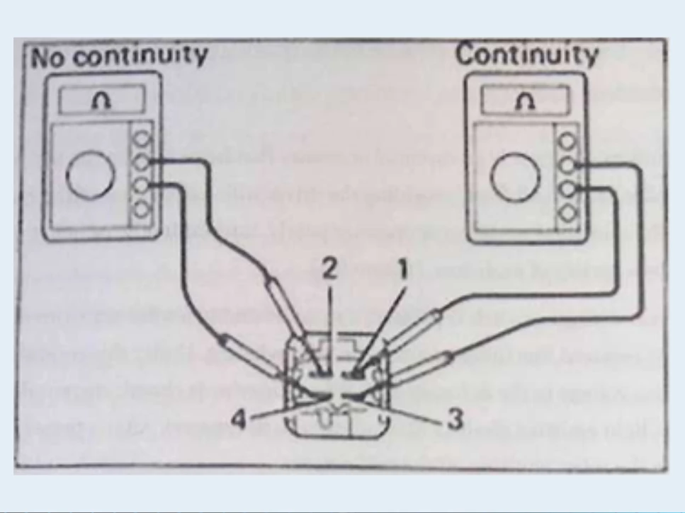
| 2 | Check the cruise control switch on the steering wheel for continuity between switch terminals. |
| 3 | Check the vehicle speed sensor (VSS) on the transmission or the rear differential. |
| 4 | Check the throttle cable for any signs of wear or damage. |
| 5 | Adjust the throttle cable to obtain a 0.0197 in (5 mm) lash in the cable. |
| 6 | Check the servo and vacuum lines for any leaks. |
| 7 | Check the electronic controller, relays, connectors, and wires for any signs of wear or damage. |
| 8 | Repair or replace any faulty components. |
Task H.2.9 - Diagnose the Cause of False, Intermittent, or No Operation of Anti-Theft System.
An anti-theft system is designed to prevent unauthorized access to a vehicle. If the system is not functioning correctly, it can cause false alarms, intermittent operation, or no operation at all.
The most common cause of false alarms is misplaced or overly adjusted sensors, such as shock sensors. Newer sensors have two-stage mechanisms that will give a warning when the first threshold is broken and sound the alarm when the second threshold is broken. Door sensors can send false signals to the alarm module if they become rusted out, or if moving parts begin to wear out.
The interior dome light circuit is usually tied into the anti-theft system to detect when a door has been opened. Some systems are tied directly into the door ajar switch, or a switch is located in the door to specifically detect when it is open. Modern factory-installed anti-theft systems use a dedicated control module or have the functions designed into an existing module.
Passive systems are designed to start the car only when the correct key is inserted into the ignition. If the correct key is not used, the system will disable the starter system, fuel delivery system, ignition system, or any or all of these systems.
Active systems usually refer to a system that arms when the system is armed or when a sequence of events happens that automatically arm the system. An active system will sound the vehicle’s horn(s) and disable the starter if it detects an attempt to break into one of its coverage zones.
These zones can include the doors, trunk, hood, ignition, and a radio input. Some systems have active ultrasonic sound waves that set up an invisible shield to protect the interiors of convertibles.
To diagnose the anti-theft system, first, check the fuses and wiring connections. Ensure that the battery is fully charged, and the vehicle’s charging system is functioning correctly. Check the key to ensure it is not worn or damaged. If the key is damaged, replace it.
Next, check the door sensors to ensure they are functioning correctly. Test the shock sensor to ensure it is not overly sensitive. Check the module and controller for any signs of wear or damage. Inspect the wiring and connectors for any signs of wear or damage. Repair or replace any faulty components.
Table actions:
| Step | Action |
|---|---|
| 1 | Check the fuses and wiring connections. |
| 2 | Ensure the battery is fully charged and the charging system is functioning correctly. |
| 3 | Check the key to ensure it is not worn or damaged. |
| 4 | Test the door sensors to ensure they are functioning correctly. |
| 5 | Test the shock sensor to ensure it is not overly sensitive. |
| 6 | Check the module and controller for any signs of wear or damage. |
| 7 | Inspect the wiring and connectors for any signs of wear or damage. |
| 8 | Repair or replace any faulty components. |
Task H.2.10 - Inspect, Test, and Repair or Replace Components, Controllers, Switches, Relays, Connectors, Sensors, and Wires of an Anti-Theft System Circuits.
The anti-theft system circuit consists of various components, including controllers, sensors, connectors, switches, and wires. If any of these components are faulty, it can cause improper operation of the anti-theft system.
To diagnose the anti-theft system circuit, first, check the wiring and connectors for any signs of wear or damage. Inspect the sensors to ensure they are functioning correctly. Test the switches to ensure they are functioning correctly. Check the relays and controllers for any signs of wear or damage.
If any of these components are faulty, repair or replace them. Ensure that the components are installed correctly and that the wiring is routed correctly.
Table actions:
| Step | Action |
|---|---|
| 1 | Check the wiring and connectors for any signs of wear or damage. |
| 2 | Inspect the sensors to ensure they are functioning correctly. |
| 3 | Test the switches to ensure they are functioning correctly. |
| 4 | Check the relays and controllers for any signs of wear or damage. |
| 5 | Repair or replace any faulty components. |
| 6 | Ensure that the components are installed correctly and that the wiring is routed correctly. |
Task H.2.11 - Diagnose the Cause(s) of the Supplemental Restraint/Airbag Warning Light Staying On or Flashing.
The supplemental restraint/airbag warning light is illuminated for five to six seconds after the engine is started while the module performs system checks. If the warning light stays illuminated, there is a fault with the airbag system. A code will be flashed through the airbag warning light when the airbag module is set to diagnostic mode. If this light also fails, the system may be set up to sound a warning tone through the warning chime system. You should also be able to retrieve codes for the system with a diagnostic tool.
To diagnose the cause of the supplemental restraint/airbag warning light staying on or flashing, first, check the wiring and connectors for any signs of wear or damage. Inspect the sensors to ensure they are functioning correctly. Test the switches to ensure they are functioning correctly. Check the relays and controllers for any signs of wear or damage.
If the components are functioning correctly, use a diagnostic tool to retrieve the codes for the system. Check the codes to determine the cause of the warning light staying on or flashing. Common causes of the warning light staying on or flashing include faulty sensors, faulty controllers, faulty wiring, or faulty connections.
Repair or replace any faulty components as necessary. Ensure that the components are installed correctly and that the wiring is routed correctly. After the repairs have been made, clear the codes using a diagnostic tool and test the system to ensure proper operation.
Table of Actions:
| Step | Action |
|---|---|
| 1 | Check the wiring and connectors for any signs of wear or damage. |
| 2 | Inspect the sensors to ensure they are functioning correctly. |
| 3 | Test the switches to ensure they are functioning correctly. |
| 4 | Check the relays and controllers for any signs of wear or damage. |
| 5 | Use a diagnostic tool to retrieve the codes for the system. |
| 6 | Check the codes to determine the cause of the warning light staying on or flashing. |
| 7 | Repair or replace any faulty components as necessary. |
| 8 | Ensure that the components are installed correctly and that the wiring is routed correctly. |
| 9 | Clear the codes using a diagnostic tool. |
| 10 | Test the system to ensure proper operation. |
Task H.2.12 - Disarm and Enable the Airbag System for Vehicle Service Following Manufacturer’s Recommended Procedures.
Disarming and enabling the airbag system is an important safety procedure that should be followed when performing any service on the vehicle. Failure to follow the manufacturer’s recommended procedures can result in serious injury or death.
To disarm the airbag system, first, disconnect the negative battery cable and tape the cable terminal to prevent accidental connection to the battery post. Then, remove the SIR fuse from the fuse box. Wait at least ten minutes to allow the reserve energy to dissipate before working on or around the airbag system.
To enable the airbag system, first, ensure that all repairs have been made and all components have been installed correctly. Then, insert the SIR fuse back into the fuse box. Reconnect the negative battery cable.
After enabling the airbag system, start the engine and check the airbag warning light to ensure it is functioning correctly. Test the airbag system to ensure proper operation.
| Step | Action |
|---|---|
| 1 | Disconnect the negative battery cable and tape the cable terminal to prevent accidental connection to the battery post. |
| 2 | Remove the SIR fuse from the fuse box. |
| 3 | Wait at least ten minutes to allow the reserve energy to dissipate before working on or around the airbag system. |
| 4 | Ensure that all repairs have been made and all components have been installed correctly. |
| 5 | Insert the SIR fuse back into the fuse box. |
| 6 | Reconnect the negative battery cable. |
| 7 | Start the engine and check the airbag warning light to ensure it is functioning correctly. |
| 8 | Test the airbag system to ensure proper operation. |
Task H.2.13 - Inspect, Test, and Repair or Replace the Airbag(S), Controllers, Sensors, Connectors, and Wires of the Airbag System Circuit(S)
The airbag system consists of various components, including airbags, controllers, sensors, connectors, and wires. If any of these components are faulty, it can cause improper operation of the airbag system.
To inspect, test, and repair or replace the airbag system components, first, disconnect the negative battery cable and wait for the manufacturer’s specified time period to elapse. This time period is usually one or two minutes. Never use a powered test light to diagnose an airbag system.
Diagnose these systems with a voltmeter or the manufacturer’s recommended diagnostic tool(s). Use of an ohmmeter should be restricted to circuits without connections to pyrotechnic devices. Since deployed airbags may contain residual chemicals, wear safety glasses and gloves when handling these components. Sensors should always be mounted in their original orientation.
Most sensors have directional arrows that must face the specified direction. Front airbag sensors are positioned toward the front of the vehicle and side airbag sensors are aimed toward the sides. Always store inflator modules face up on the bench and carry these components with the trim cover facing away from your body.
To inspect the airbags, visually inspect them for any signs of damage, including rips, tears, or punctures. If the airbags are damaged, they must be replaced.
To test the airbag system, use a diagnostic tool to retrieve any stored codes. Check the codes to determine the cause of any issues with the airbag system. Inspect the sensors, controllers, connectors, and wires for any signs of wear or damage. Use a voltmeter or diagnostic tool to test the components for proper function.
If any components are faulty, repair or replace them as necessary. Ensure that the components are installed correctly and that the wiring is routed correctly. After the repairs have been made, clear any stored codes using a diagnostic tool.
Table of Actions:
| Step | Action |
|---|---|
| 1. | Disconnect the negative battery cable and wait for the manufacturer’s specified time period to elapse. |
| 2. | Never use a powered test light to diagnose an airbag system. |
| 3. | Diagnose these systems with a voltmeter or the manufacturer’s recommended diagnostic tool(s). |
| 4. | Use of an ohmmeter should be restricted to circuits without connections to pyrotechnic devices. |
| 5. | Wear safety glasses and gloves when handling these components. |
| 6. | Inspect the airbags for any signs of damage, including rips, tears, or punctures. |
| 7. | Use a diagnostic tool to retrieve any stored codes. |
| 8. | Inspect the sensors, controllers, connectors, and wires for any signs of wear or damage. |
| 9. | Use a voltmeter or diagnostic tool to test the components for proper function. |
| 10. | Repair or replace any faulty components as necessary. |
| 11. | Ensure that the components are installed correctly and that the wiring is routed correctly. |
| 12. | Clear any stored codes using a diagnostic tool. |
| 13. | Test the airbag system to ensure proper operation. |
Task H.2.14 - Diagnose the Cause of Improper Operation of Motorized Seat Belts.
Motorized seat belts operate similarly to power windows, except that the driver and passengers have no control over the motor’s action. Improper operation of the motorized seat belts can be caused by several issues, including faulty motors, switches, modules, and limit switches.
To diagnose the cause of improper operation of motorized seat belts, first, check the fuses, motors, and the module if both seat belts are inoperative. If only one seat belt is inoperative, check the door ajar switches, motor, module, and the front and rear limit switches for defects.
Check the door tracks for binding mechanisms and/or debris that could be hindering the system. If the seat belt will not stop trying to move when it reaches the stop point on the door, check the limit switch on that door and then the module.
Table of Actions:
| Step | Action |
|---|---|
| 1 | Check the fuses, motors, and the module if both seat belts are inoperative. |
| 2 | If only one seat belt is inoperative, check the door ajar switches, motor, module, and the front and rear limit switches for defects. |
| 3 | Check the door tracks for binding mechanisms and/or debris that could be hindering the system. |
| 4 | If the seat belt will not stop trying to move when it reaches the stop point on the door, check the limit switch on that door and then the module. |
If these initial checks do not reveal the cause of the issue, inspect the motors, solenoids, switches, tracks, controllers, connectors, and wires of the motorized seat belt system circuit(s) for any signs of wear or damage. Use a diagnostic tool or voltmeter to test the components for proper function.
If any components are found to be faulty, repair or replace them as necessary. Ensure that the components are installed correctly, and that the wiring is routed correctly. After the repairs have been made, test the motorized seat belt system to ensure proper operation.
Table of Actions:
| Step | Action |
|---|---|
| 1. | Inspect the motors, solenoids, switches, tracks, controllers, connectors, and wires of the motorized seat belt system circuit(s) for any signs of wear or damage. |
| 2. | Use a diagnostic tool or voltmeter to test the components for proper function. |
| 3. | Repair or replace any faulty components as necessary. |
| 4. | Ensure that the components are installed correctly and that the wiring is routed correctly. |
| 5. | Test the motorized seat belt system to ensure proper operation. |
In conclusion, the ASE A6 test task list includes several tasks related to accessory diagnosis and repair. These tasks demand a comprehensive understanding of the electronic components and systems associated with these accessories, as well as the utilization of specialized diagnostic tools and equipment.
By adhering to the recommended procedures and employing the appropriate tools and techniques, technicians can proficiently diagnose and repair these accessories, guaranteeing the safe and dependable operation of the vehicle.
The Key Takeaways
To inspect, test, adjust, and repair or replace components of the cruise control system, technicians should follow the manufacturer’s instructions and ensure the proper adjustment of the cruise control cable.
When diagnosing false, intermittent, or no operation of the anti-theft system, technicians should check sensors, switches, and circuits for defects and understand how the system should work before proceeding. In inspecting, testing, and repairing the anti-theft system, technicians should use a wiring diagram and parts locator guide to diagnose issues and treat the circuit like any other electrical circuit.
When diagnosing issues with the supplemental restraint/airbag warning light, technicians should use a diagnostic tool to retrieve any stored codes and inspect sensors, controllers, connectors, and wires for any signs of wear or damage.
To disarm and enable the airbag system for vehicle service, technicians should follow the manufacturer’s instructions, disconnect the negative battery cable, and wait for the specified time period to elapse. When diagnosing improper operation of motorized seat belts, technicians should check fuses, motors, and modules, as well as door tracks and limit switches, and inspect the motorized seat belt system circuit for any signs of wear or damage.
Summary
In this chapter, we covered several tasks related to accessory diagnosis and repair for ASE A6 technicians. The tasks included inspecting, testing, adjusting, repairing, or replacing various components, controllers, switches, relays, connectors, sensors, and wires of cruise control circuits, diagnosing the cause of false, intermittent, or no operation of anti-theft systems, inspecting, testing, and repairing or replacing components, controllers, switches, relays, connectors, sensors, and wires of anti-theft system circuits, diagnosing the cause(s) of the supplemental restraint/airhag warning light staying on or flashing, disarming and enabling the airbag system for vehicle service following manufacturers recommended procedures, diagnosing the cause of improper operation of motorized seat belts, and inspecting, testing, and repairing or replacing motors, solenoids, switches, tracks, controllers, connectors, and wires of motorized seat belts.
To effectively diagnose and repair these accessories, technicians must follow the recommended procedures and use specialized diagnostic tools and equipment. Proper inspection and testing of these components can help ensure the safe and reliable operation of the vehicle.
Good Luck!
👉 You may also like - The complete ASE practice test with answers and explanations
👉 You may also like - Mastering ASE Testing - The Ultimate Guide for Success
👉 You may also like - Mastering Electrical and Electronic Systems Diagnosis
👉 You may also like - Batteries - The Heart of Vehicle Power - Diagnosis and Service
👉 You may also like - Ignition Unveiled - Starting System Diagnosis and Repair
👉 You may also like - Keeping Current - Charging System Diagnosis and Repair
👉 You may also like -Illuminating the Road - Lighting Systems Diagnosis and Repair
👉 You may also like - Monitoring and Alert Systems - Gauges, Warnings, and Driver Info Diagnosis
👉 You may also like - Sounding Off - Horn and Wiper/Washer Systems Diagnosis


